
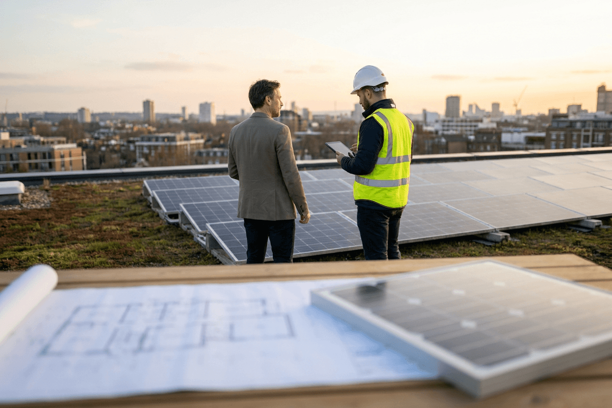

Across the United Kingdom, rooftop solar photovoltaic (PV) arrays have evolved from optional green add-ons into foundational components of low-carbon building design. Accelerated by stringent Part L revisions, the Future Homes Standard, and net-zero commitments across local authorities, solar panels now crown everything from landmark commercial retrofits to high-density social housing. Yet, beneath the clean energy headlines lies an acute regulatory and technical challenge: the escalating fire risk associated with rooftop PV installations and the heightened statutory liabilities now resting on architects acting as Principal Designers under the Building Safety Act regime.
According to an authoritative technical examination published on solar PV rooftop fire risks, specifying solar infrastructure is no longer a simple matter of handing roof plans over to an MEP subcontractor. In an era where fire performance, structural safety, and long-term asset management are under rigorous regulatory scrutiny, architectural practitioners must bridge the gap between decarbonisation targets and fire safety engineering.
The Dual Imperative: Balancing Decarbonisation with Fire Safety
The imperative to integrate on-site renewable microgeneration has never been stronger. As industry leaders and built environment practitioners gather at forums like London Build 2026 to debate the next frontier of sustainable housing delivery, digital design transformation, and circular building envelopes, the integration of renewables remains central to UK decarbonisation roadmaps.
Nowhere is this more evident than in exemplary civic and council-led developments. Projects such as the RIBA Neave Brown Award 2026 winner—the Rowan Court scheme in Seven Sisters, designed by Satish Jassal Architects for Haringey Council—demonstrate how high-density, low-carbon social housing must harmonise architectural delight, robust brick craftsmanship, and clean energy generation. Delivering 46 council homes with exceptional thermal performance and rooftop technology, schemes of this calibre prove that sustainability cannot come at the expense of life safety or long-term operational resilience.
However, introducing high-voltage direct current (DC) electrical systems onto building envelopes introduces distinct risk profiles that architects must proactively manage during early design stages.
Understanding the Anatomy of Rooftop Solar PV Fire Risks
Photovoltaic arrays present unique fire challenges because, unlike standard alternating current (AC) domestic circuits, PV panels generate live DC electricity whenever exposed to light. Even if a building's main switchboard is isolated, the DC cables between the array and the inverter remain live—a condition known across the fire safety sector as the “DC hazard zone.”
“A solar array is a live electrical generator that cannot simply be turned off at the main switch. When combustible roofing substrates, inadequate DC cabling containment, and restricted firefighter access coincide, a minor electrical fault can rapidly escalate into an uncontainable roof fire.”
Architects must account for three primary failure mechanisms when developing rooftop layouts and technical specifications:
- DC Arc Faults: The primary ignition source in PV systems. Faulty connectors, micro-cracks in panels, poor cable crimping, or mechanical damage (from wind shear or vermin) can create high-temperature electrical arcs exceeding 3,000°C, capable of igniting underlying roofing membranes.
- Chimney Effect and Flame Spread: Flat and pitched solar mounting frames create an air gap between the panel and the roof surface. If a fire starts underneath, this gap creates a convective chimney effect that accelerates lateral flame spread beneath the panels, bypassing conventional roof fire breaks.
- Impaired Firefighting Operations: Fire and Rescue Services (FRS) face serious electric shock risks when applying water to live DC arrays. Furthermore, extensive PV coverage often obstructs roof access, smoke venting, and safe firefighter transit.
The Principal Designer's Statutory Mandate
Following the enactment of the Building Safety Act 2022 and updates to Part B (Fire Safety) of the Building Regulations, the role of the Principal Designer has expanded significantly. Architectural practices can no longer treat rooftop PV as a specialist contractor design portion (CDP) left uncoordinated until the construction phase.
The Principal Designer is legally required to plan, manage, and monitor the pre-construction phase to ensure that all design work coordinates fire safety and eliminates reasonably foreseeable risks. In the context of rooftop PV, this requires deep coordination across structural, architectural, electrical, and fire engineering disciplines.
| Design Parameter | Traditional Approach | Principal Designer Best Practice (Post-BSA) |
|---|---|---|
| Roof Substrate & Insulation | Standard PIR/PUR insulation with combustible single-ply membrane. | Euroclass A1 or A2-s1, d0 non-combustible insulation (e.g., stone wool) directly beneath PV zones. |
| FRS Access & Walkways | Panels packed across 90%+ of roof area to maximise kilowatt-peak (kWp). | Dedicated 1.0m to 1.5m non-combustible maintenance and FRS access perimeters around PV clusters. |
| Electrical Isolation | Manual isolators located only adjacent to ground-level or plant-room inverters. | Module-level power electronics (MLPE) or rapid shutdown systems initiating micro-second de-energisation at the panel level. |
| Compartmentation | Continuous PV arrays crossing over internal compartment walls. | Physical breaks and non-combustible buffer zones aligned with underlying vertical fire compartment walls. |
Technical Design Principles for Resilient Rooftop PV
1. Substrate Selection and Reaction to Fire Classifications
Under Approved Document B and insurance industry benchmarks (such as RISCAuthority RC62 recommendations), the roof build-up beneath PV installations must resist external fire exposure. Architects should specify roofing assemblies tested to BROOF(t4) classification in accordance with BS EN 13501-5. Where combustible insulation or waterproofing is present, incorporating non-combustible barrier boards or stone wool core layers beneath the mounting frames acts as an essential thermal and fire barrier.
2. Managing the Spatial Geometry and Compartmentation
Rooftop solar layouts must never bridge internal compartment walls. If a fire breaches the roof deck in one compartment, continuous PV arrays can carry the fire across the roof to adjacent tenancies or building cores. Architectural plans must incorporate a minimum clear corridor of 1.5 metres above all structural compartment lines, kept entirely clear of panels, cabling, and mounting hardware.
3. Cable Routing, Inverters, and Rapid Shutdown
DC cabling represents an enduring ignition hazard if routed carelessly through internal voids. Best practice dictates running DC cables along external, fire-resistant pathways or within dedicated non-combustible steel trunking. Furthermore, specifying micro-inverters or DC optimisers equipped with automated rapid shutdown technology ensures that voltage drops below safe thresholds (typically under 30V within 30 seconds) the moment the AC supply is severed or the emergency FRS switch is triggered.
4. The Golden Thread and Asset Handover
Crucially, the statutory duties of the Principal Designer culminate in the assembly of the Golden Thread of Information and the Regulation 38 fire safety handover pack. For rooftop PV, this documentation must provide the building owner, responsible person, and local fire service with precise “as-built” drawings showing DC conduit runs, rapid shutdown switch locations, module capacities, and mandatory maintenance schedules to prevent degraded connectors from triggering arcing events years into operation.
The Path Forward: Designing with Clarity and Rigour
As UK architecture accelerates its trajectory toward a zero-carbon built environment, the integration of rooftop microgeneration is set to multiply across residential towers, schools, commercial offices, and civic landmarks. However, sustainability that compromises life safety is fundamentally flawed design.
By stepping confidently into their Principal Designer duties, mastering the physics of electrical roof fire risks, and enforcing rigorous spatial and material standards, architects can deliver buildings that are as safe and enduring as they are sustainable.